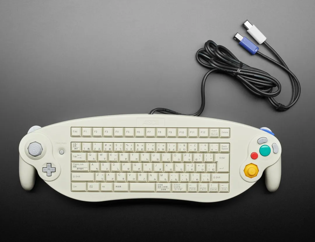
Gamecube ASCII controller USB Retrofit
(April 2026 - )
1. PRESENTATION
There is this rather obscure piece of hardware called the GameCube ASCII Controller. It was made specifically for Phantasy Star Online and was only released in Japan. Since the GameCube was a big part of my childhood, and I also happen to be a keyboard enthusiast, this felt like the perfect excuse for another funky project. The idea is to replace the original PCBs and turn the whole thing into a regular USB device — basically doing the same thing I did with my keypad. The PC should see it as both a keyboard and an Xbox controller.
If you haven't already, I recommend reading the Keypad page first, as this project borrows quite a few ideas from it.
Just like the keypad, I'll use two microcontrollers: one for the keyboard side, running QMK, and another for the XInput side, running Arduino on a specialized ATmega32U4 setup with a custom USB descriptor. The two controllers will talk to each other over UART at 115200 baud. It's no DMA SPI, but it'll do. As long as they can exchange everything without any noticeable latency, that's good enough for this project.
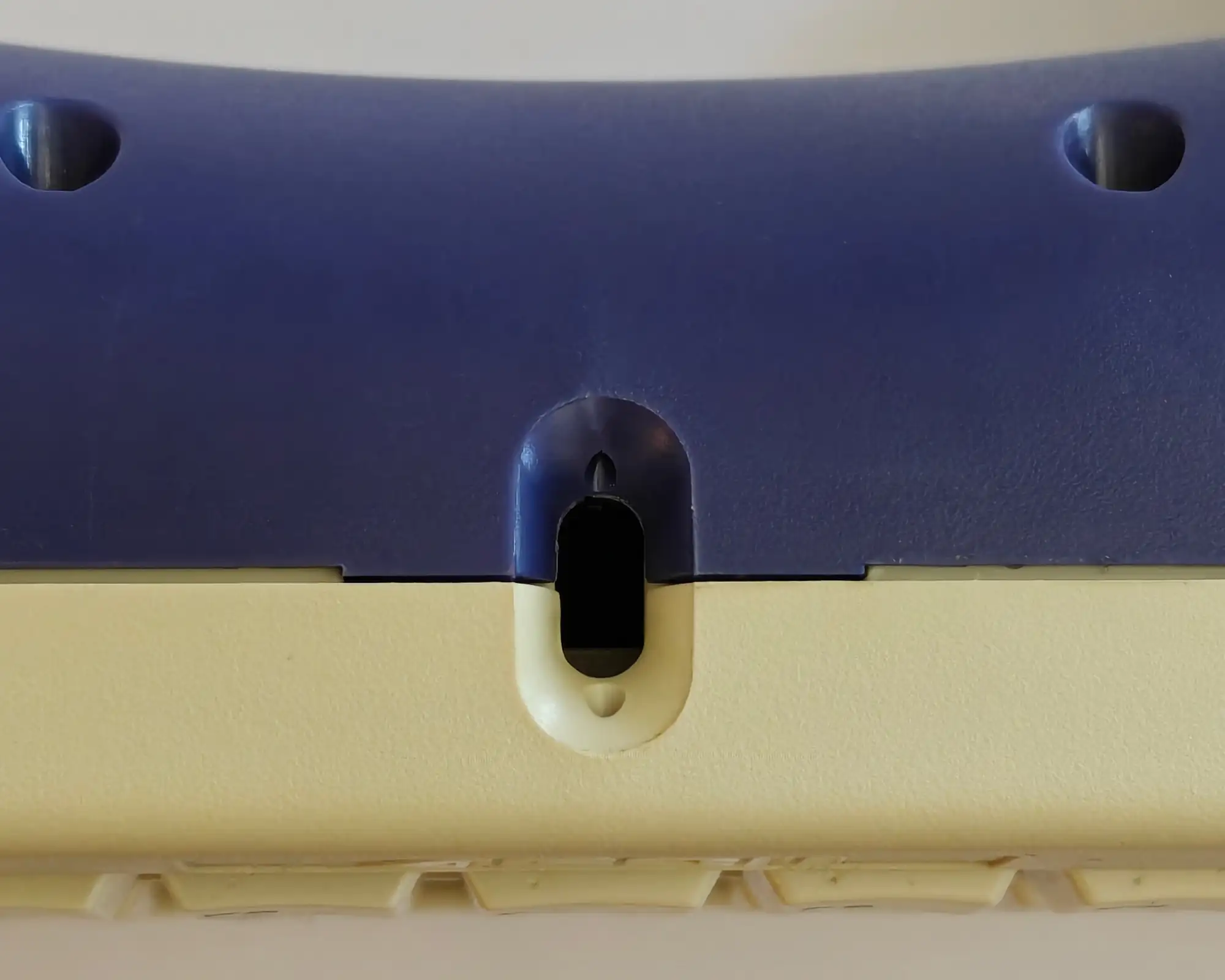
The USB hub, combining the USB connections from both controllers, will be connected to a small daughterboard that will sit neatly behind this suspiciously USB-C-looking hole, where the main cables used to be :
2. THE OUTLINE (EDGE.CUT)
First, I desoldered every through-hole component. Then, armed with my trusty Mitutoyo caliper, I measured all around to determine the shapes and dimensions of the three PCBs in this controller. I designed the three pieces in SolidWorks and printed them in PLA to verify that they accurately replicated the original PCBs.
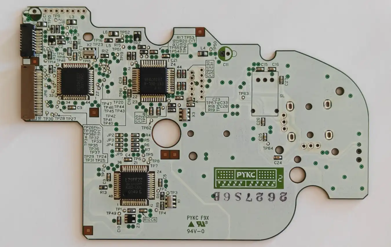
Left side, bottom view
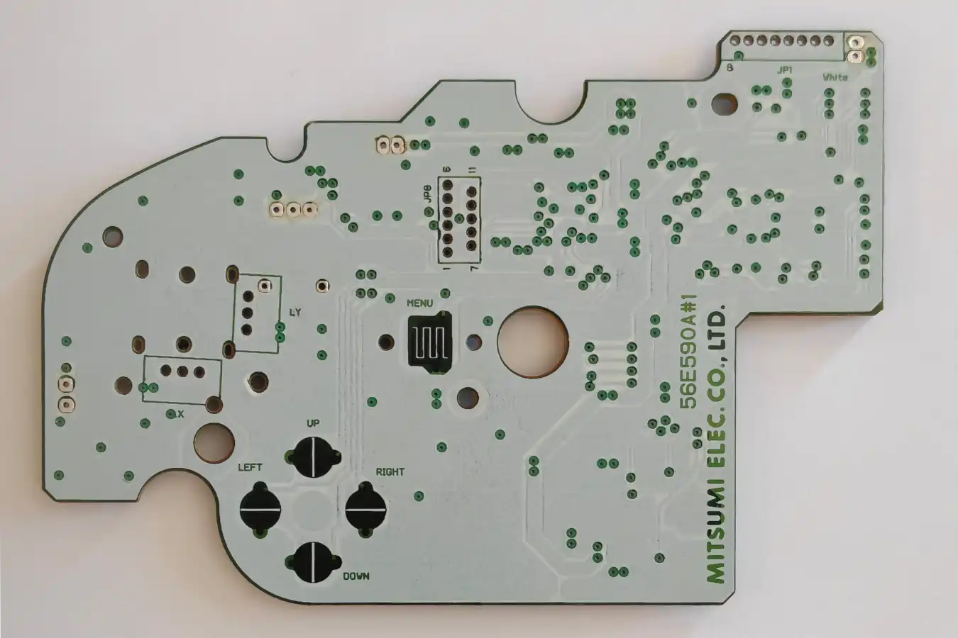
Left side, top view
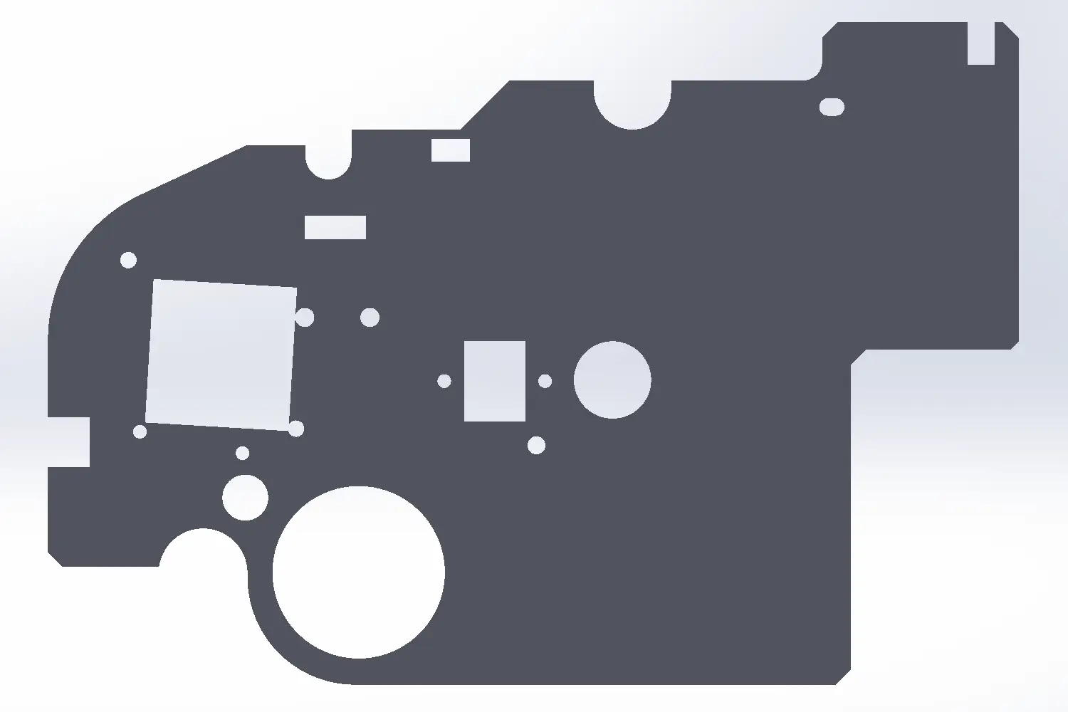
Left side, STL
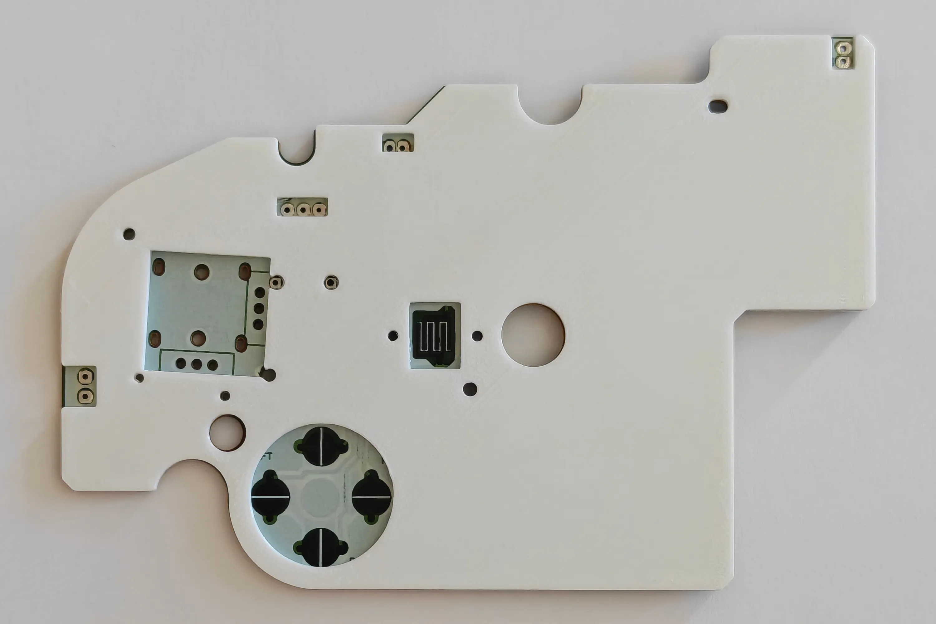
Left side, STL on top of the PCB
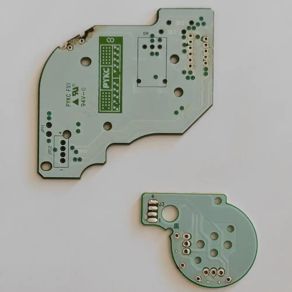
Right side, bottom view
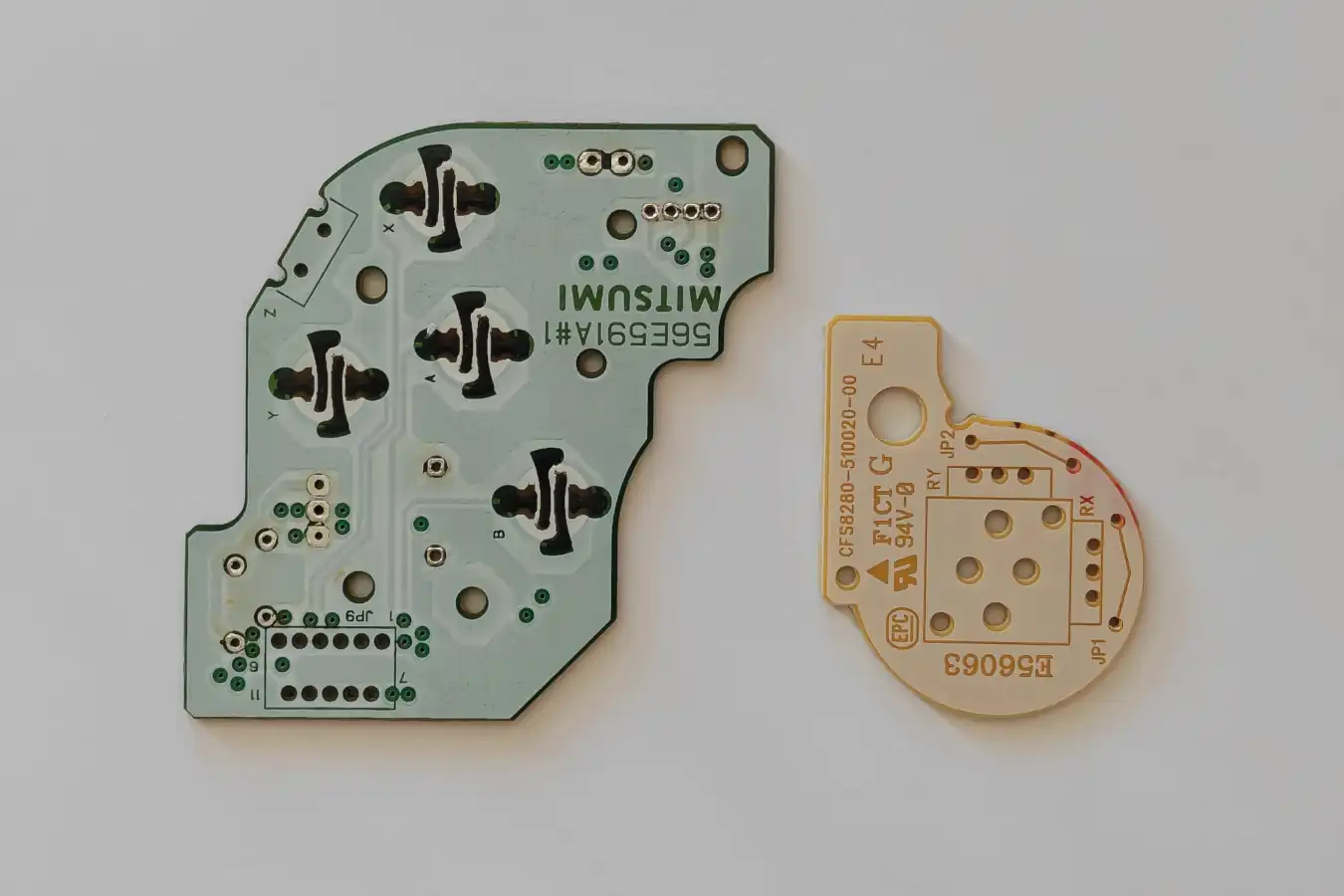
Right side, top view

Right side, STL

Right side, STL
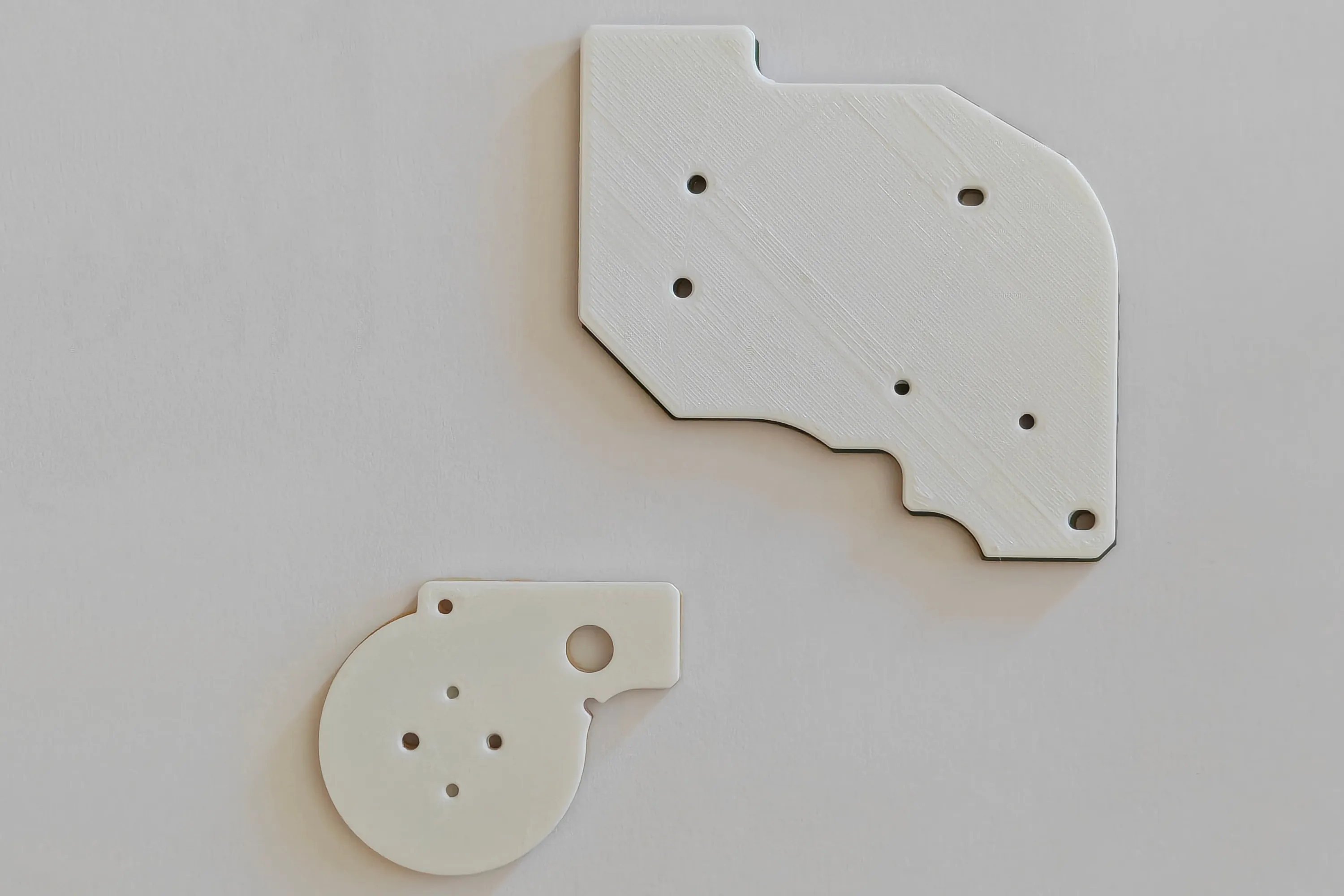
Right side, STL on top of the PCB
I will make multiple revisions of the PCBs. A first one with no parts or assembly. Once I am comfortable with how it fits together, I will order the populated and assembled version.
3. DESIGNING
The basic architecture is fairly straightforward: the keyboard side runs QMK, while the controller side handles XInput. The main challenge is fitting everything onto the replacement PCBs while keeping the original mechanical layout intact. I use an I2C I/O expander since lots of pins are needed for the keyboard matrix
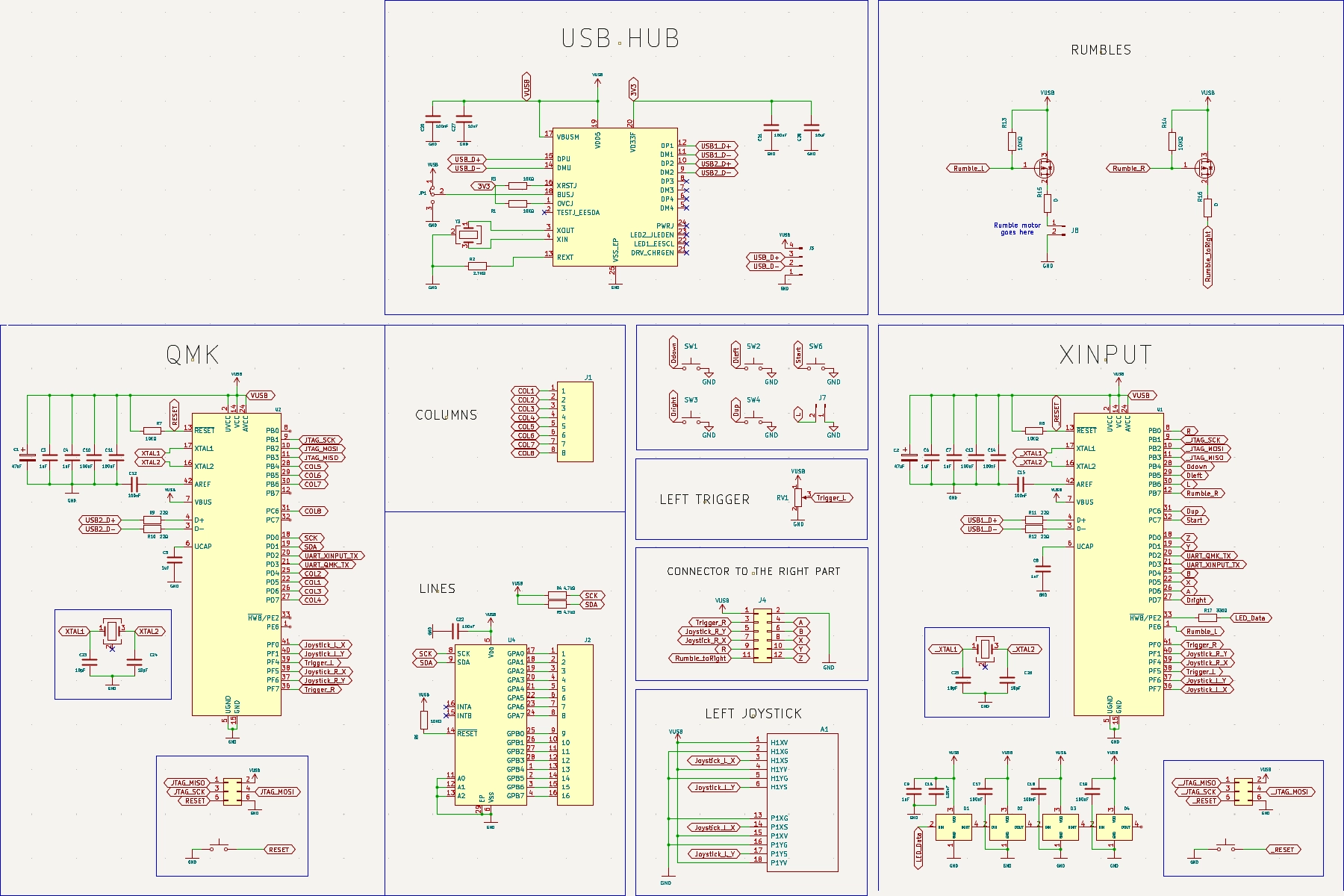
Schematic. Click to view full size
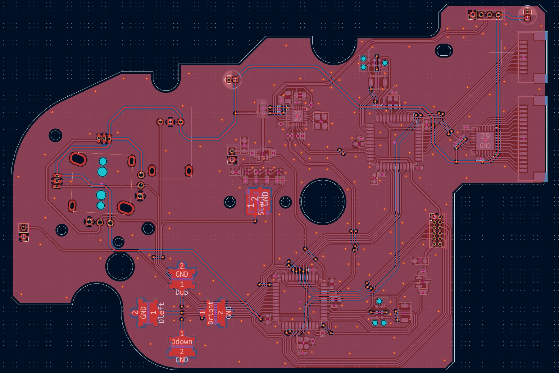
PCB top view. Click to view full size
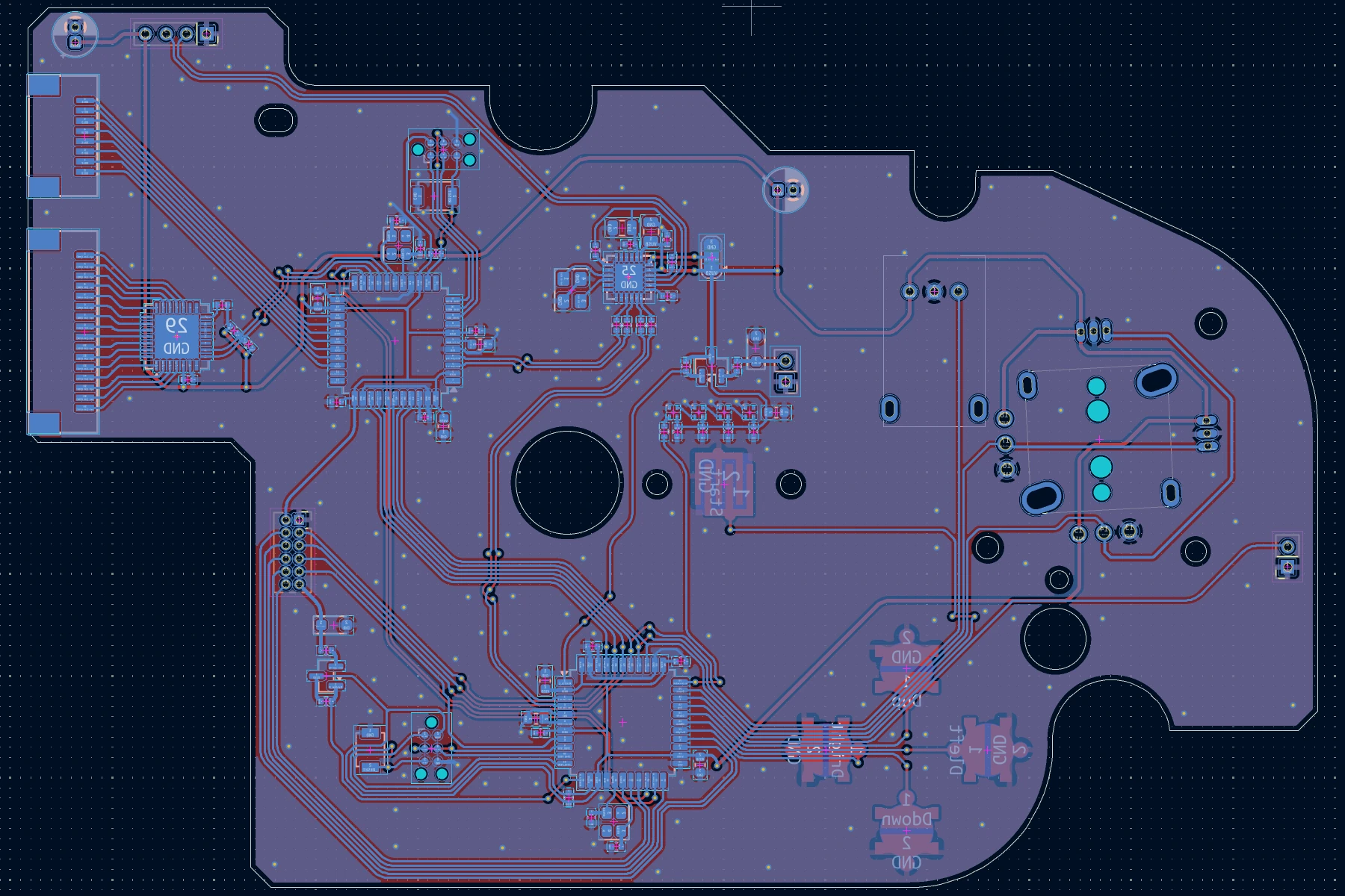
PCB bottom view. Click to view full size
4. FIRST BATCH
Ordered from JLCPCB. Arrived 3 weeks later.
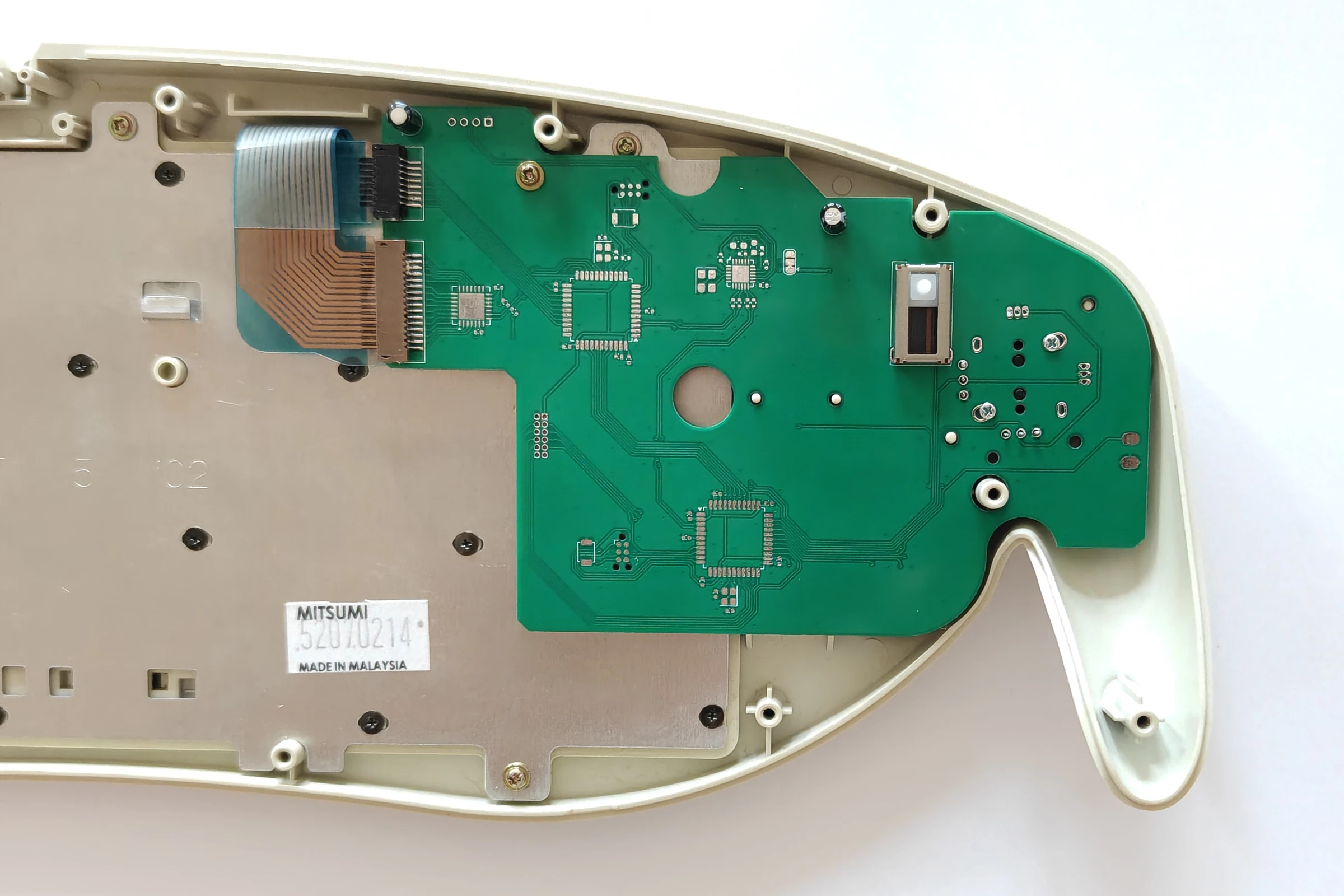
Left PCB. Click to view full size
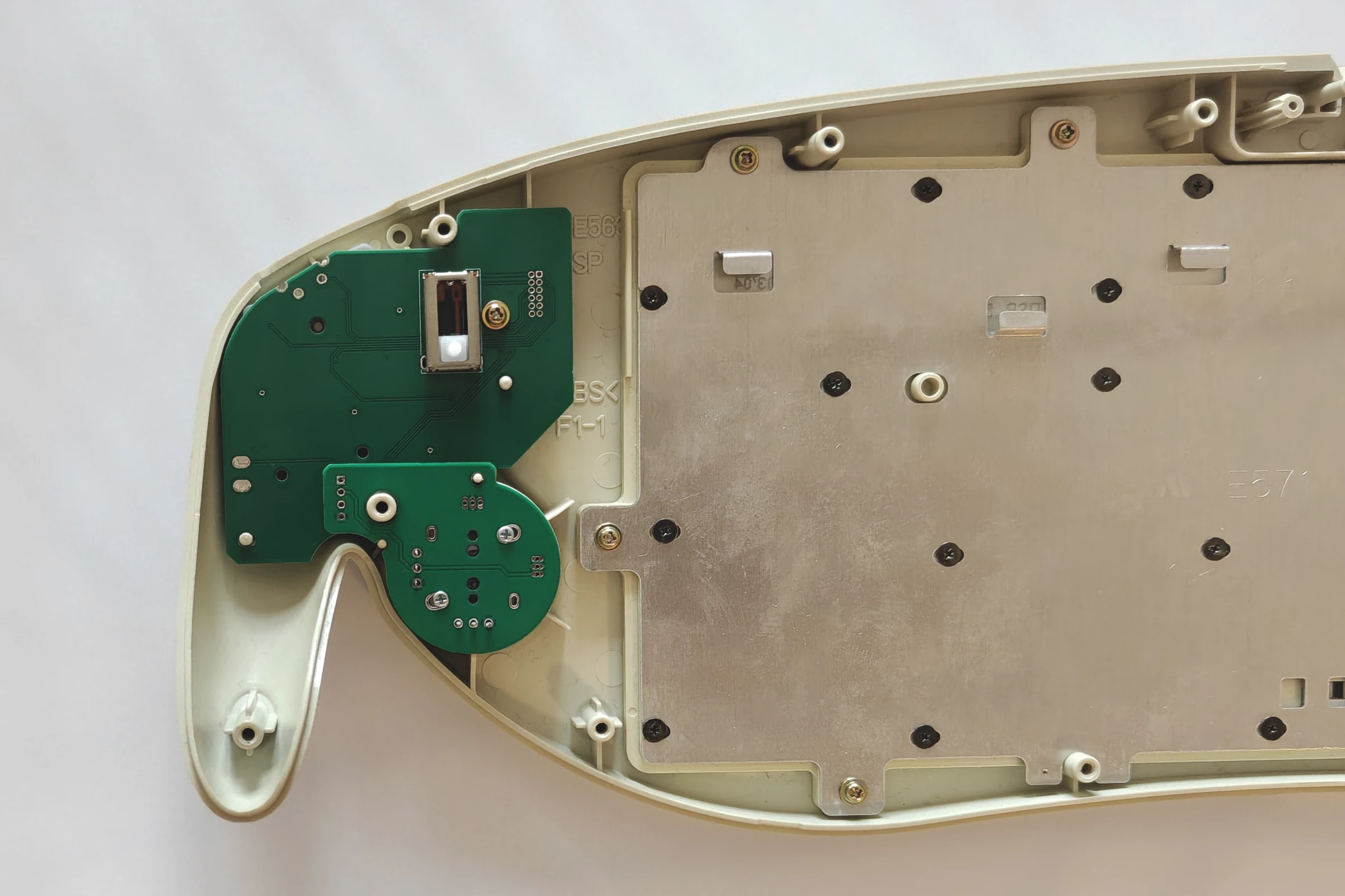
Righ and joystick PCB. Click to view full size
The measurements where mostly good. I have two things to fix.
The left joystick was positionned/measured a bit too low so I had to raise it up by 0.5mm.
The Z button was not positionned correctly. The PCB cannot be inserted when I place the Z button, and can certainly not be pressed.
I shifted it by 1.75mm to the exterior.
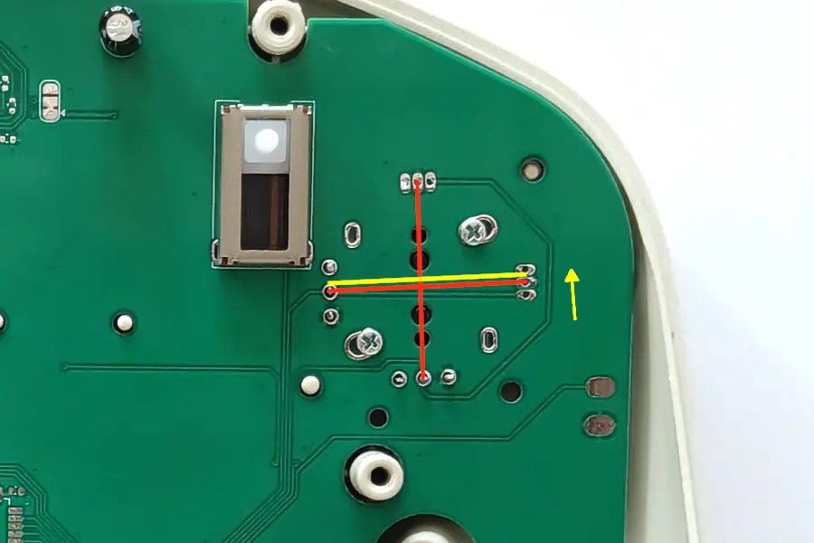
Left joystick shift
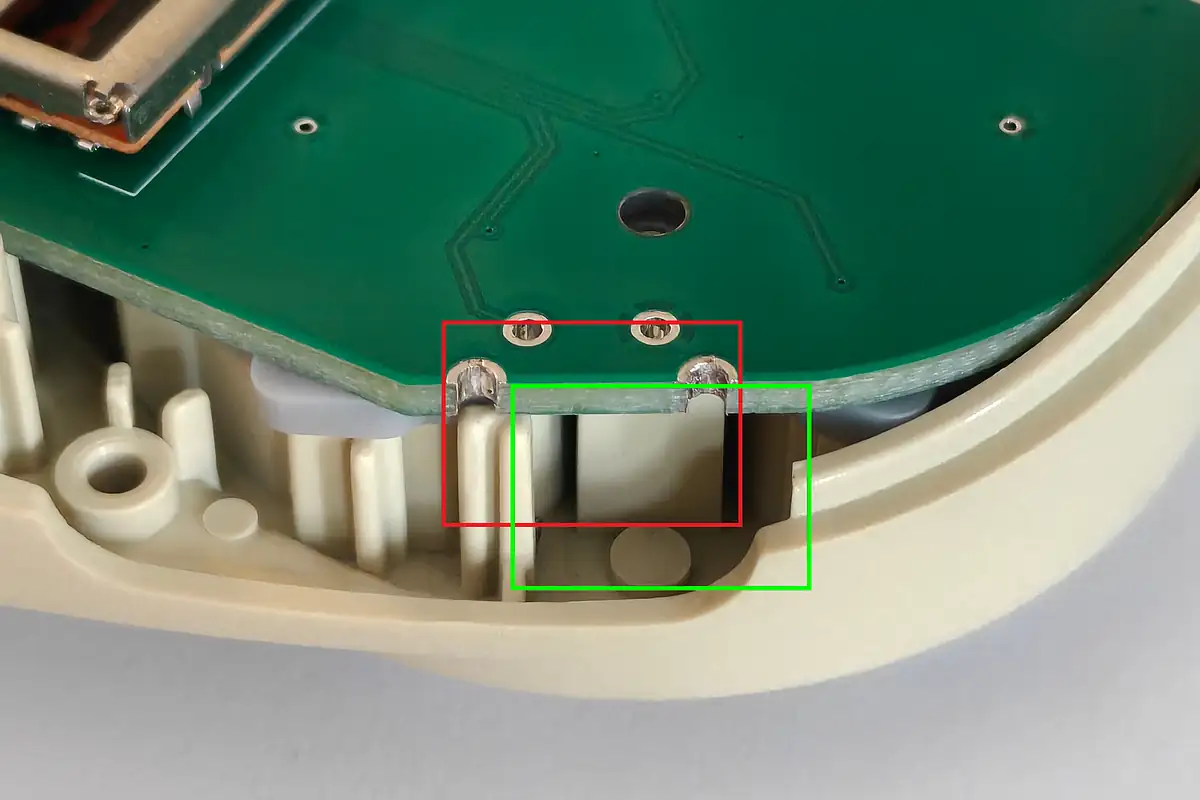
Z button eror
5. SECOND BATCH - WITH ASSEMBLY
Ordered from JLCPCB. En route. Only the bottom side of the left part needs assembly, keeping the cost reasonable.
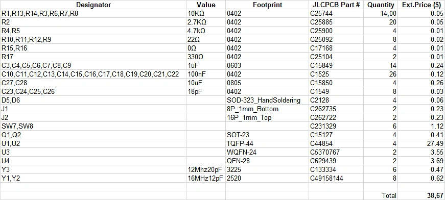
BOM. Click to view full size
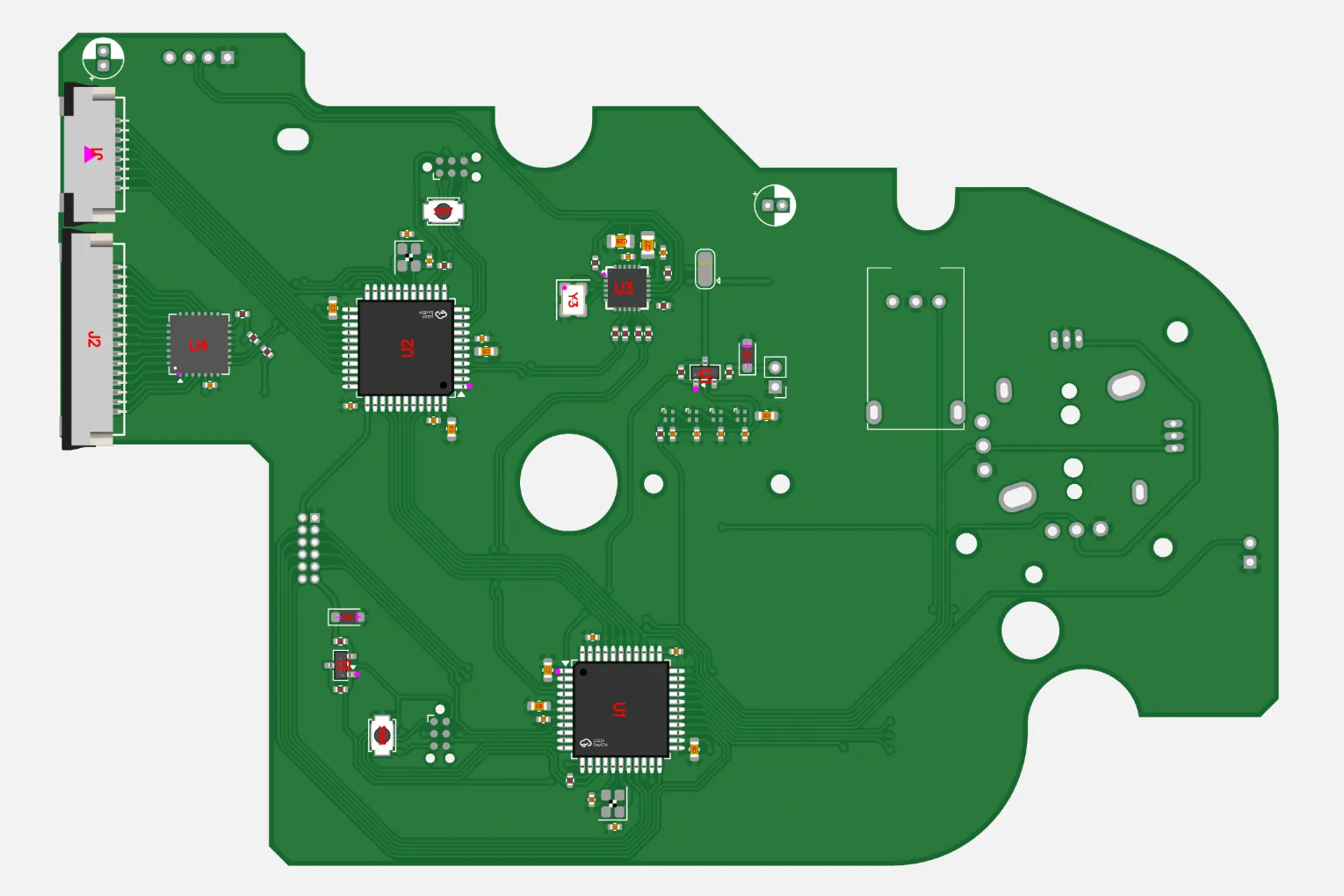
PCBA. Click to view full size